 |
 |
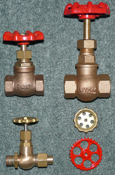
Fitting new steam valves
 The photo shows the various
steam valves that I have investigated for use on my Stafford. The photo shows the various
steam valves that I have investigated for use on my Stafford.At the top left is one of the original steam valves as fitted to my Stafford and the two other engines of production Batch One. This valve has a metal cone attached to the spindle which seats into a machined hole in the main body casting. The valve also has a fibre gasket (you can just see the red gasket in the photo) between the main valve body and the top spindle section. As explained in the problems section of this website the metal to metal valve contact can be damaged by over tightening causing steam to leak past the valve, and the fibre gasket became hardened with repeated steamings and eventually started to break up. These two reasons were why I needed to replace all four steam valves on my Stafford. The valve at the top right is one of the valves fitted to all Stafford locomotives built after Batch One, and as can be seen it is considerably taller and a bit wider than the original valve. The "globe" section of the main body is also visibly larger than its predecessor. The first benefit of this new valve is that it has a PTFE valve seat which gives much better sealing when the valve is closed and is much more damage resistant than the original valves metal to metal seal. The second benefit is that it no longer has the fibre gasket that I found to be failing after prolonged use of my locomotive. I actually purchased four of these valves to fit to my Stafford but never fitted them simply because they looked too big on the engine. I know that they work perfectly well and that most Stafford owners are happy with them, but I decided to investigate what else was available. The valve at the bottom left of the photo is manufactured by R A Barker and is a manifold globe valve incorporating a PTFE valve seat that is designed for use with output pipes of either 5/16" or 3/8" diameter (8mm or 9.5mm). On paper this valve looked suitable for use on the Stafford, and a phone call to the manufacturers confirmed that it would be suitable to operate a No 5 injector (the size fitted to my Stafford when built by Station Road Steam). As a result I purchased some valves to test. I fitted these valves in sequence to the vacuum brake ejector, the steam blower, and finally to the left hand injector; testing the loco between fitting each valve to see how well they worked. On the vacuum brake ejector and steam blower the valves were a big improvement over the originals simply because they opened less per turn than the original valves and thus controlled the steam flow much better. This was a very significant benefit on the vacuum brake ejector which had always proved to be difficult to adjust for the low steam flow needed to simply maintain the vacuum on the coaches used at Pinewood. On the steam blower the new valve also allowed the flow of steam to be adjusted easier, using almost 1/2 a turn of the valve hand wheel as opposed to just a few degrees on the original valve. This much finer control caused me some concern before I fitted one of the valves to the left hand injector as I wondered if it may be difficult to start the injector. However no problems were seen when the valve was fitted and the valve showed itself to be a suitable replacement. My only concern was the hand wheel supplied with the valve. As seen at the bottom right of the photo it was a simple brass disc with a few holes in it. The red hand wheel is one of the set that I made for the Stafford and if you wish to read about how I made them please click here. |
|
 This
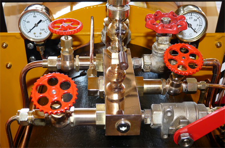
photo shows my Stafford with three of the R A Barker manifold globe
valves fitted and you can easily see how much smaller they are than the
original steam valve (at the top right) let alone the much taller
"current style" valves. So far I am very pleased with the
conversion and everyone who has looked at the loco has commented how
much better they look than what they describe as "the rather large
original valves". The valves are much easier to operate than
the
standard Stafford valves, both in the amount of effort needed to turn
the hand wheels and in the way they control the steam. The
hand
wheels I made also seem to remain decently cool when the loco is
operating, much as Station Road Steam had intended with their choice of
valve. The only problem is that these valves cost about three
times as much as the current valve from Station Road Steam. This
photo shows my Stafford with three of the R A Barker manifold globe
valves fitted and you can easily see how much smaller they are than the
original steam valve (at the top right) let alone the much taller
"current style" valves. So far I am very pleased with the
conversion and everyone who has looked at the loco has commented how
much better they look than what they describe as "the rather large
original valves". The valves are much easier to operate than
the
standard Stafford valves, both in the amount of effort needed to turn
the hand wheels and in the way they control the steam. The
hand
wheels I made also seem to remain decently cool when the loco is
operating, much as Station Road Steam had intended with their choice of
valve. The only problem is that these valves cost about three
times as much as the current valve from Station Road Steam.Fitting the valves was reasonably easy, as is explained below in case anyone wants to make the conversion on their engine, and for the vacuum ejector and steam blower the valves connected directly to the existing pipe connectors with the aid of suitable adaptors. The injector valve needed a completely new steam pipe to feed the injector as there was no way to fit the valve with an adaptor to the existing pipe without moving the valve much closer to the steam manifold and whistle (which I didn't want to do). Since writing this page the final valve has been fitted to the right hand injector and no problems have been seen as a result of the conversion. The injector is still very easy to start and control, although you do have to remember to open the valve using a couple of turns of the hand wheel as opposed to less than half a turn with the original valve due to the much finer control of the new valve. Only you as a Stafford owner can decide if the cost of this conversion is worthwhile, but I am very happy with the new valves. |
|
A step by step guide to fitting R A Barker globe valves to a Stafford steam engine. 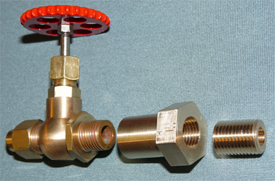 The
valves I purchased where all ordered with 1/4" BSP threads on the input
side and an adaptor for 5/16" diameter pipe on the outlet side.
As
a result they could have simply been screwed into the existing tapped
holes in the steam manifold but I chose to fit spacers so that there
was more space to get a hand around the controls. This photo
shows the two parts of the spacers. I chose to make the
spacer in
two parts because my first attempt at undercutting the spacer thread
where it met the hexagonal section resulted in (to my eyes at least)
insufficient turns of thread for a good fixing. As I could
not
extend the length of the threaded section due to the design of the
steam manifold, and my die would not cut the thread any closer to the
hexagon the two piece design solved both problems (and was probably
easier to make as well). Ideally the spacers should be made
from
gunmetal or phosphor bronze to ensure they have a long working life,
but to test the new valves I made the parts using brass as a cheaper
option. The
valves I purchased where all ordered with 1/4" BSP threads on the input
side and an adaptor for 5/16" diameter pipe on the outlet side.
As
a result they could have simply been screwed into the existing tapped
holes in the steam manifold but I chose to fit spacers so that there
was more space to get a hand around the controls. This photo
shows the two parts of the spacers. I chose to make the
spacer in
two parts because my first attempt at undercutting the spacer thread
where it met the hexagonal section resulted in (to my eyes at least)
insufficient turns of thread for a good fixing. As I could
not
extend the length of the threaded section due to the design of the
steam manifold, and my die would not cut the thread any closer to the
hexagon the two piece design solved both problems (and was probably
easier to make as well). Ideally the spacers should be made
from
gunmetal or phosphor bronze to ensure they have a long working life,
but to test the new valves I made the parts using brass as a cheaper
option.The threaded section at the right is simply a connector made from a length of bar with a 1/4" BSP thread cut along its length and a 7mm hole drilled right through it. The centre spacer section is made from a length of 7/8" hexagonal bar. An 11.5mm diameter hole was drilled 16 mm deep into one end and tapped1/4" BSP to a depth of 12mm. The end was then faced off and a further 0.1mm turned off the length so that the hexagon "edges" were relieved to leave a smooth circular mating face. The metal was then reversed in the lathe chuck and faced off until it was about 31mm long. An 11.5mm hole was then drilled through to meet the existing hole and tapped 1/4" BSP to a depth of 13mm. Finally the end was faced off to leave a finished length of 30mm, and a length of 21mm was turned down to 17.5mm diameter. The reason for this method of manufacture was to ensure that the threaded holes were truly perpendicular to the end faces and that the faces were clean with no burrs caused by cutting the threads. This is important as each end will have to make a steam tight joint with the parts they mate with. |
|
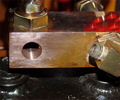 The
next step is to remove the existing steam valve from the manifold.
To do so you need to separate the spindle assembly from the
main
body by unscrewing it, and then after removing the associated output
steam pipe you can unscrew the main valve body and its adaptors from
the steam manifold. At this point the steam manifold will
look
something like the photo, but you will probably find that part of the
rim of the threaded hole is no longer flat. This is caused by
the
steam manifold having distorted when the original adaptor had been
screwed tightly into place on its tapered thread. As the new
valve adaptor is intended to have a steam tight seal against this
surface you will need to use Swiss Files and an Emery block to remove
any "bumps". In the photo you can just see a different
coloured
(textured) area around the threaded hole where the surface has been
smoothed. The
next step is to remove the existing steam valve from the manifold.
To do so you need to separate the spindle assembly from the
main
body by unscrewing it, and then after removing the associated output
steam pipe you can unscrew the main valve body and its adaptors from
the steam manifold. At this point the steam manifold will
look
something like the photo, but you will probably find that part of the
rim of the threaded hole is no longer flat. This is caused by
the
steam manifold having distorted when the original adaptor had been
screwed tightly into place on its tapered thread. As the new
valve adaptor is intended to have a steam tight seal against this
surface you will need to use Swiss Files and an Emery block to remove
any "bumps". In the photo you can just see a different
coloured
(textured) area around the threaded hole where the surface has been
smoothed.You will also probably need to pick bits of old sealant out of the threaded hole and eventually to run a 1/4" BSP tap into the hole, using your fingers and not a tap wrench as you only want to clean the thread and not cut it any deeper. Once cleaned up use a powerful vacuum cleaner to suck all the debris out of the threaded hole as you will not want any of it to find its way into your injectors or ejector ! The new threaded connector is then screwed into the hole using Green Hermatite (or another suitable steam jointing compound) for about half of its length. The hexagonal section then screws onto the connector, again using Green Hermatite, and is securely tightened against the steam manifold. The spindle assembly of the new steam valve then has to be removed from the valve body so that the body section can be screwed into the hexagonal spacer, this time using some PTFE tape wound onto the valve body thread to seal the joint. Once the valve is correctly aligned the thin locknut is tightened to lock the valve body into position. Finally the spindle assembly is then refitted again using Green Hermatite. |
|
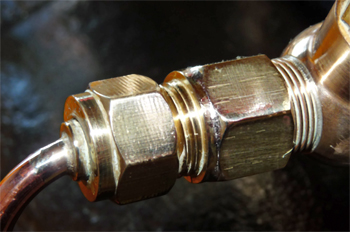
 All
that remains is to sort out the connection between the steam pipes and
the new valves. For the vacuum ejector it is easy to turn up
a
replacement pipe adaptor akin to that supplied with the steam valve
that has a threaded section to attach the existing steam pipe.
This is possible simply because the pipe connector thread is
small enough to fit through the new R A Barker valve output pipe gland
nut.
The photo shows how a new "Top Hat pipe connector was turned with a
5/16"x32 Model Engineers thread to suit the original pipe gland nut.
The length of the threaded section was made to locate the
vacuum
ejector pipe in the correct position. All
that remains is to sort out the connection between the steam pipes and
the new valves. For the vacuum ejector it is easy to turn up
a
replacement pipe adaptor akin to that supplied with the steam valve
that has a threaded section to attach the existing steam pipe.
This is possible simply because the pipe connector thread is
small enough to fit through the new R A Barker valve output pipe gland
nut.
The photo shows how a new "Top Hat pipe connector was turned with a
5/16"x32 Model Engineers thread to suit the original pipe gland nut.
The length of the threaded section was made to locate the
vacuum
ejector pipe in the correct position. |
|
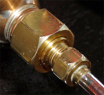
 For
the steam blower I resorted to silver soldering a 1/4" BSP
threaded bush, with an 11mm diameter by 4mm long extension that fitted
through the hole
into the valve output gland nut, onto the end of the output gland nut.
This threaded bush was drilled through at 4mm diameter which
was
slightly larger than the bore of the blower steam pipe. When
the
assembly was screwed into place on the valve the 4mm
extension tightened against the valve output face and created the steam
tight joint. The photo shows how a 16mm diameter by 2mm wide
shoulder provides the mating face for soldering to the R A Barker valve
output pipe gland nut, and this also sets the correct spacing so that
the blower pipe is located in its correct position. For
the steam blower I resorted to silver soldering a 1/4" BSP
threaded bush, with an 11mm diameter by 4mm long extension that fitted
through the hole
into the valve output gland nut, onto the end of the output gland nut.
This threaded bush was drilled through at 4mm diameter which
was
slightly larger than the bore of the blower steam pipe. When
the
assembly was screwed into place on the valve the 4mm
extension tightened against the valve output face and created the steam
tight joint. The photo shows how a 16mm diameter by 2mm wide
shoulder provides the mating face for soldering to the R A Barker valve
output pipe gland nut, and this also sets the correct spacing so that
the blower pipe is located in its correct position. |
|
| For
the two injectors I could find no
way to refit the existing pipes, so I had to resort to making a new
pair of steam pipes. The only problem here was that the cab
sides
and reversing lever assembly had to be removed to extract the
old
pipes and to feed the new ones
into position. Finally I fitted my new hand wheels to replace those supplied by R A Barker. |