 |
 |
The saga of the Mechanical
Lubricator
| If you have read the problems pages of this website you will have already seen references to the mechanical lubricator, but it has been the subject of a lot of work over almost eighteen months. This page details the work done for Gentoo, but depending on which production batch your Stafford originates from you will certainly find differences between your loco's fit and what is described here. NOTE: By the end of 20111 Station Road Steam had developed their own mechanical lubricator which has an even larger oil capacity than the one described below. Like my lubricator it uses roller clutches, but it is mounted in a new location on the left hand side of the loco. Unfortunately this new lubricator cannot easily be retrofitted to Stafford's built with the original small capacity lubricator. | |
 As described in the problems
pages the lubricator as supplied was difficult to fill with oil and
seeing the oil level in it was almost impossible as the lubricator was
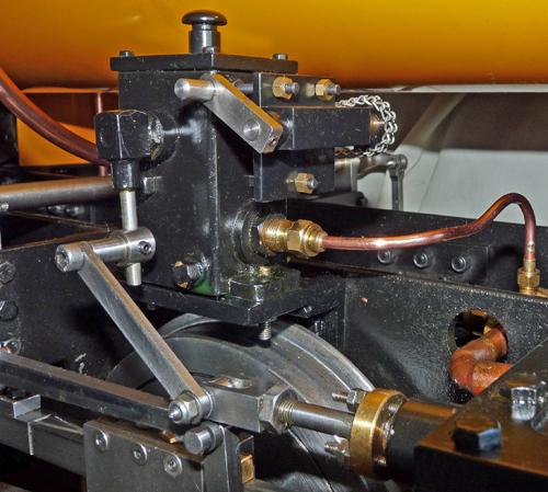
hidden underneath the saddle tank. The photo on the left
shows the original lubricator in its final configuration on my Stafford. As described in the problems
pages the lubricator as supplied was difficult to fill with oil and
seeing the oil level in it was almost impossible as the lubricator was
hidden underneath the saddle tank. The photo on the left
shows the original lubricator in its final configuration on my Stafford.The first modification was to simply make a new lid which was clipped as opposed to bolted in place. This was made from mild steel to give it some "mass" and had four 6 BA hex head screws fitted with their threaded ends turned down almost smooth which slid into the original lid bolt holes. The remains of the threads gave a nice little bit of friction to help hold the lid in place, and when the lid was lifted off it was much easier to see inside the lubricator oil tank. This work was all completed before the Stafford was first taken to the track in September 2010. However the limited running we had at the end of 2010 showed that access to the tank was still difficult and that the manual operating handle was really inaccessible under the saddle tank. Trying to reach through from the left to operate the winder while not touching the hot steam pipe was almost impossible. So before running again at the start of 2011 the lubricator was removed and modified as shown in the photo. The right angle mounting bracket was replaced with one having a longer top surface so that the lubricator could be moved further outboard. This was achieved by swapping the lubricator operating link from the chassis side of the slide valve clevis to the outside (as shown on the photo) and also by shortening the round crank arm that connects the lubricator arm to the operating link. It may have only moved the lubricator outwards by about 18 mm (3/4") but it made a big difference to access for filling it with oil. The other modification involved a visit to my scrap box to salvage some old Meccano chain and gears. As shown in the photo this allowed the operating handle to be moved to the outside of the lubricator for easy access. The new crank handle shaft plate was mounted to the lubricator using three lengths of 4 BA studding so that the chain tension could be easily adjusted. 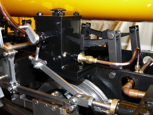 The photo on the right shows the replacement lubricator that I built after the original lubricator ceased operating correctly (see the problems pages). This lubricator was made using a length of 50 x 50 x 3 aluminium square section tubing welded to an aluminium base plate, and increased the oil capacity to over twice that of the original. This in itself was worth the work as it now holds sufficient oil for over 12 miles of running, so the driver rarely needs to top up the oil level during the day. If you want to try to build this lubricator yourself you will find the AutoCAD Lt drawing file "linked" at the bottom of this page. It was all made using my small lathe and pillar drill (no milling involved) although I did get the aluminium welding done by a local engineering company. The design uses roller clutches (from an e-bay bearing supplier) instead of the ratchet pawls of the original lubricator so it works far more smoothly and is easier to adjust when setting up, and as you can see the manual winder is on the outside for easy access. As before the lid simply slips in place using extensions of the four 4 BA bolts visible on the lid to slide inside the aluminium body. The one surprise when I built it was that the small pump ram return spring (which was quite soft and easy to compress) actually had enough power to force the operating crank to "free wheel" rapidly through most of the return cycle. This would have resulted in a lubricator that was pumping oil almost continuously as opposed to the normal 50 / 50 cycle, and would probably have pumped too much oil. Thankfully my design included an 'O' ring on the operating shaft to stop the steam oil leaking out of the shaft bearing, and once this was compressed into position the friction overcame the spring's action so that the lubricator operated satisfactorily. If you copy my design you need to make sure that the components that fit inside the lubricator along the shaft give some compression of the 'O' ring. At the time of writing this page in early January 2012 I now that Station Road Steam are working on a new lubricator of their own design, so it will be interesting to see what the next batch of Stafford's are fitted with. For those of you who have CAD on your computer you can download my CAD drawing in .dwg format by right clicking on the link below and then saving the file on your computer. Please note that the drawing is predominantly metric and is drawn full size. Gentoo's Journals provides the drawing "for guidance only" and does not guarantee its accuracy or completeness. You should also note that the drawing is not dimensioned, simply because it was produced first as a concept drawing, and then revised to show what was actually built in my workshop. Right click here for the CAD .dwg file. |
|