 |
 |
Restoring the Mardyke petrol
hydraulic Hymek locomotive D7031
 As
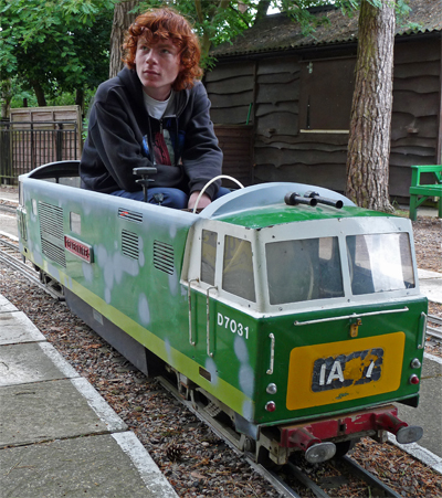
I owned the Stafford steam locomotive 'Gentoo' you may wonder why I
would want to purchase the rather decrepit looking loco in this photo.
With its battered and rusty body, badly worn and random
diameter
wheels, brake system components dragging on the track, and a totally
dysfunctional electrical system it had obviously seen better days.
However it did run well and I could see its
potential as a useful loco for the Pinewood Miniature Railway, even if the only way to stop
the petrol
engine was to break a wire and "earth" the bare end. A
deal was soon arranged and the next week the loco was dismantled with
the expectation
of completing the restoration in about 4 to 5 months. A full
year
later the loco is finally almost ready to run and I have time to write
this page about it. As
I owned the Stafford steam locomotive 'Gentoo' you may wonder why I
would want to purchase the rather decrepit looking loco in this photo.
With its battered and rusty body, badly worn and random
diameter
wheels, brake system components dragging on the track, and a totally
dysfunctional electrical system it had obviously seen better days.
However it did run well and I could see its
potential as a useful loco for the Pinewood Miniature Railway, even if the only way to stop
the petrol
engine was to break a wire and "earth" the bare end. A
deal was soon arranged and the next week the loco was dismantled with
the expectation
of completing the restoration in about 4 to 5 months. A full
year
later the loco is finally almost ready to run and I have time to write
this page about it.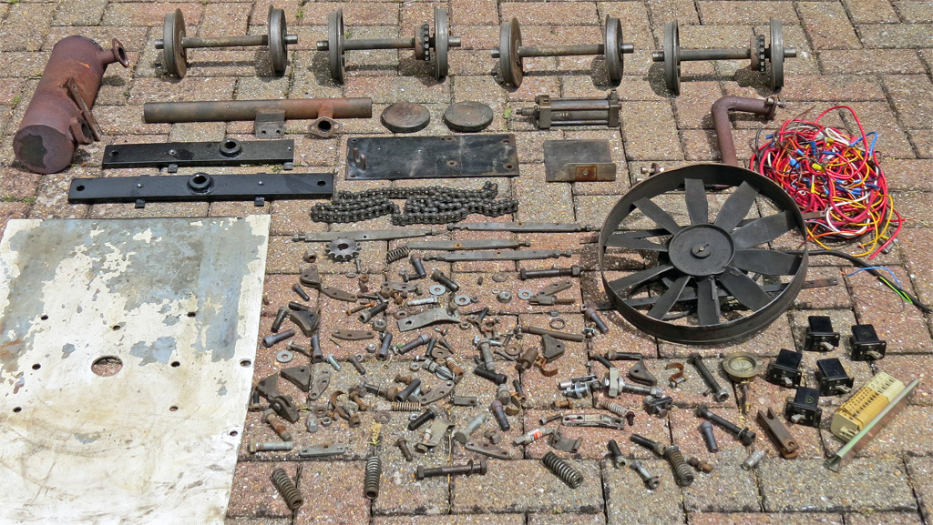 Research showed that the loco named 'Temeraire' was built in 1989 (so it was much younger than I imagined) and that Mardyke are still trading today, which was useful as I could purchase some parts as "off the shelf" spares. The photo on the left taken after the loco had been rebuilt shows the parts from my "for possible use bucket". All these parts, and a lot more that were too bad to even be considered for reuse, ended up in the scrap bin. Without the Internet it would probably have been impossible to rebuild the Hymek and even so it often took hours of searching to find a supplier for some of the rarer BSF and BSW nuts and bolts. As usual the restoration went well over budget; however the end result is not only a useful loco but the preservation of an engine produced by Mardyke that may otherwise have disappeared. During my research into the history of this Hymek I learnt of other Mardyke Hymeks that were being scrapped as "beyond economic repair" so preserving this one to me at least has been worthwhile. The following sections of this page show some of the major components of the Hymek in "before and after" photos to give an idea of the work involved in the restoration. But if you only want to see some photos of the finished Hymek, now renamed 'Dark Star' then please click here. |
The Power Bogie |
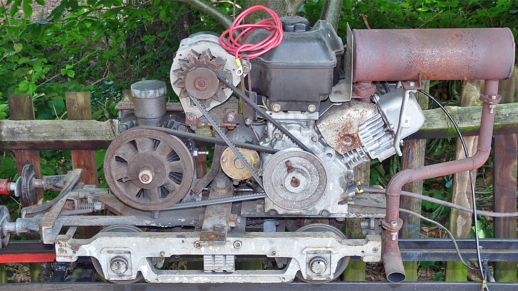 This
photo shows the power bogie from 'Temeraire' just after it had been
extracted from the Hymek. Above the right hand wheel is the
Briggs
& Stratton 206cc 6.5 Hp petrol engine with the Eaton
No 7
Hydrostatic Transmission to its left. The rusty exhaust was
not
original Mardyke but had been built by a previous owner, and as we
discovered during the locos test drive it very quickly roasted the
drivers back. The alternator (top centre) was also non
standard
and had probably been fitted to supply the power required by the large
engine bay cooling fan and the air brake pump, both of which were also
non standard. This
photo shows the power bogie from 'Temeraire' just after it had been
extracted from the Hymek. Above the right hand wheel is the
Briggs
& Stratton 206cc 6.5 Hp petrol engine with the Eaton
No 7
Hydrostatic Transmission to its left. The rusty exhaust was
not
original Mardyke but had been built by a previous owner, and as we
discovered during the locos test drive it very quickly roasted the
drivers back. The alternator (top centre) was also non
standard
and had probably been fitted to supply the power required by the large
engine bay cooling fan and the air brake pump, both of which were also
non standard.As the power bogie was dismantled it became apparent that both of the aluminium drive pulleys on the engine had worn so far that the new drive belts I had purchased were running on the flat bottom of the pulley as opposed to gripping in the "V". New pulleys weren't too hard to find, but they had to be bored, faced, and reamed to fit; and keyways had to be cut. I also discovered that the mounting bracket for the Hydrostatic drive was welded in such a way that the pump was not aligned to the bogies axis with the result that both the belt and chain drives operated through angles. As the bracket could not easily be removed and rewelded I opted for tapered wedges to align the Hydrostatic drive. Thankfully the drive pulley on the engine could be got into correct alignment by facing its boss to the correct length. Mardyke were able to supply new wheel sets fitted with axles and drive sprockets from stock as well as the axle bearings, and consumable spares (spark plug, air filter etc.) for the Briggs & Stratton engine came from the local mower shop. The correct silencer for the engine was also quite easy to obtain, but I had to have the exhaust pipe bent to my own drawing from 1" diameter by 16 swg steel pipe by Merlin Motorsport. For some reason the new sprocket for the Hydrostatic unit supplied by Mardyke would not fit so a suitable sprocket and chain were obtained from Parkside Electronics. Both the engine and Hydrostatic drive were flushed through several times with fresh oil until it ran clear when drained to remove the "black stuff" that may once have been oil. All the metal components of the bogie were grit blasted, primed, and repainted before reassembly and you can see the completed power bogie in the photos below. My thanks go to Simon from All Welding Work in Kingsley Hampshire for the nice job he did on these bogie parts. 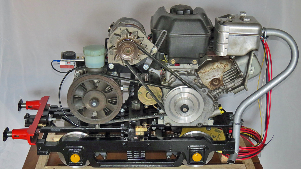 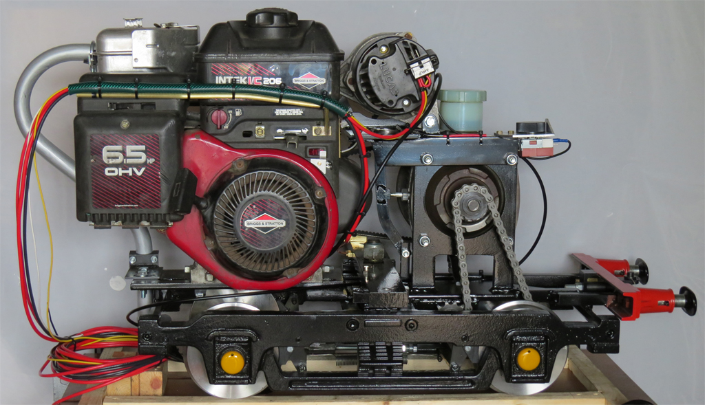 |
The Unpowered Bogie |
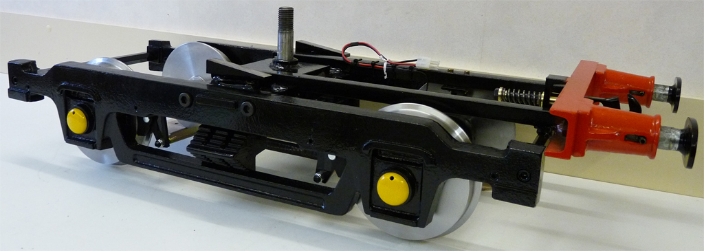 The
unpowered bogie was treated in the same fashion as its powered
counterpart with new wheel sets, roller bearings, and braking
components
being assembled into the repainted frames. However once it
was
reassembled the buffer beam looked too bare without any fittings on it
so I decided to add some detail. Space for detailing was very
limited by the design of the bogie (and the fact that it is not
"scale") but I managed to add a brake hose, electrical connector, and
the 3 link coupling which at least give the impression of a detailed
buffer beam. The
unpowered bogie was treated in the same fashion as its powered
counterpart with new wheel sets, roller bearings, and braking
components
being assembled into the repainted frames. However once it
was
reassembled the buffer beam looked too bare without any fittings on it
so I decided to add some detail. Space for detailing was very
limited by the design of the bogie (and the fact that it is not
"scale") but I managed to add a brake hose, electrical connector, and
the 3 link coupling which at least give the impression of a detailed
buffer beam. |
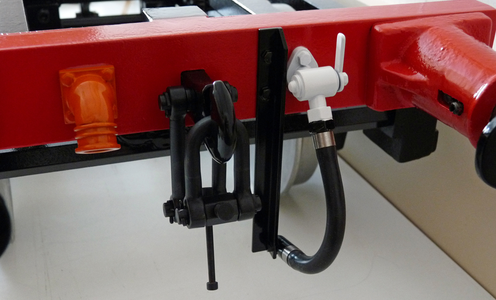 This
photo shows the completed buffer beam which despite only having a
couple of items fitted is already quite full. Full size
Hymeks
have a lot more items fitted to them but this is not a scale model, and
much of the apparent blank space has welded parts behind the buffer
beam making it impossible to attach additional detail. This
photo shows the completed buffer beam which despite only having a
couple of items fitted is already quite full. Full size
Hymeks
have a lot more items fitted to them but this is not a scale model, and
much of the apparent blank space has welded parts behind the buffer
beam making it impossible to attach additional detail. |
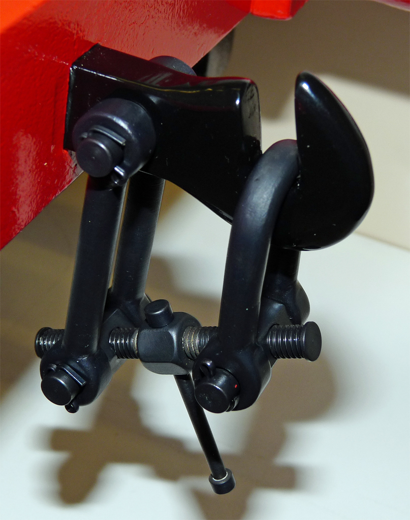 Here's
a picture of the 3 Link Coupling that I built using a photo of a
coupling fitted to the "Atlas" wagon that supports us when I'm working
on the Mid Hants Railway permanent way gang. It only took a
couple of hours to make, and the obvious error is thankfully very hard
to spot. What's the error ? Well the eagle eyed may
spot that the screw link does not
have the requisite left and right handed threads, but I have no idea
where you could obtain left hand BA taps and dies. Here's
a picture of the 3 Link Coupling that I built using a photo of a
coupling fitted to the "Atlas" wagon that supports us when I'm working
on the Mid Hants Railway permanent way gang. It only took a
couple of hours to make, and the obvious error is thankfully very hard
to spot. What's the error ? Well the eagle eyed may
spot that the screw link does not
have the requisite left and right handed threads, but I have no idea
where you could obtain left hand BA taps and dies. |
The Control Panel |
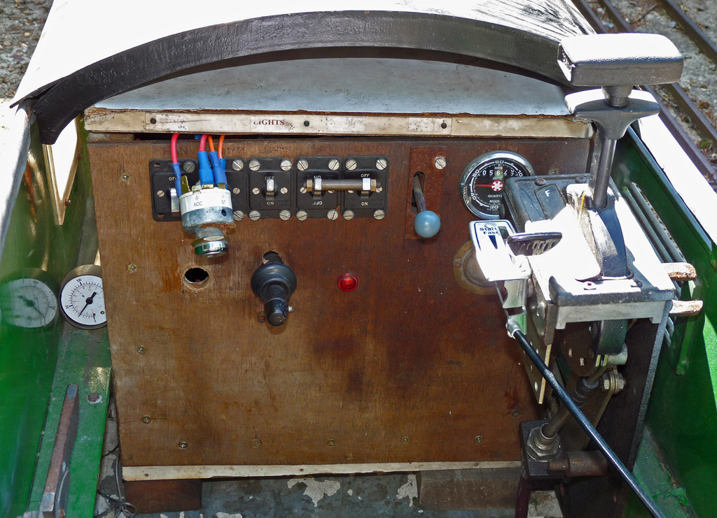 This photo shows the control panel fitted to
the Hymek when I purchased it and I'm pretty sure that Mardyke never
built it
! Most of the large box was constructed from melamine faced
MDF
sheet which (having got wet) was falling apart, and the plywood front
panel had two gauges sited to be invisible to the driver and a third
gauge was wedged in the gap to the left of the control box.
Inside the box the wiring was very neatly installed, but the
box
also held the main locomotive battery and the entire air brake system.
All of the latter components were rattling around loose
inside
the box and impossible to remove without disturbing the wiring.
The entire assembly was in such a poor state that it just had
to
be scrapped, but only after I had painstakingly worked out and drawn
circuit diagrams for it all to enable me to rebuild it. This photo shows the control panel fitted to
the Hymek when I purchased it and I'm pretty sure that Mardyke never
built it
! Most of the large box was constructed from melamine faced
MDF
sheet which (having got wet) was falling apart, and the plywood front
panel had two gauges sited to be invisible to the driver and a third
gauge was wedged in the gap to the left of the control box.
Inside the box the wiring was very neatly installed, but the
box
also held the main locomotive battery and the entire air brake system.
All of the latter components were rattling around loose
inside
the box and impossible to remove without disturbing the wiring.
The entire assembly was in such a poor state that it just had
to
be scrapped, but only after I had painstakingly worked out and drawn
circuit diagrams for it all to enable me to rebuild it. |
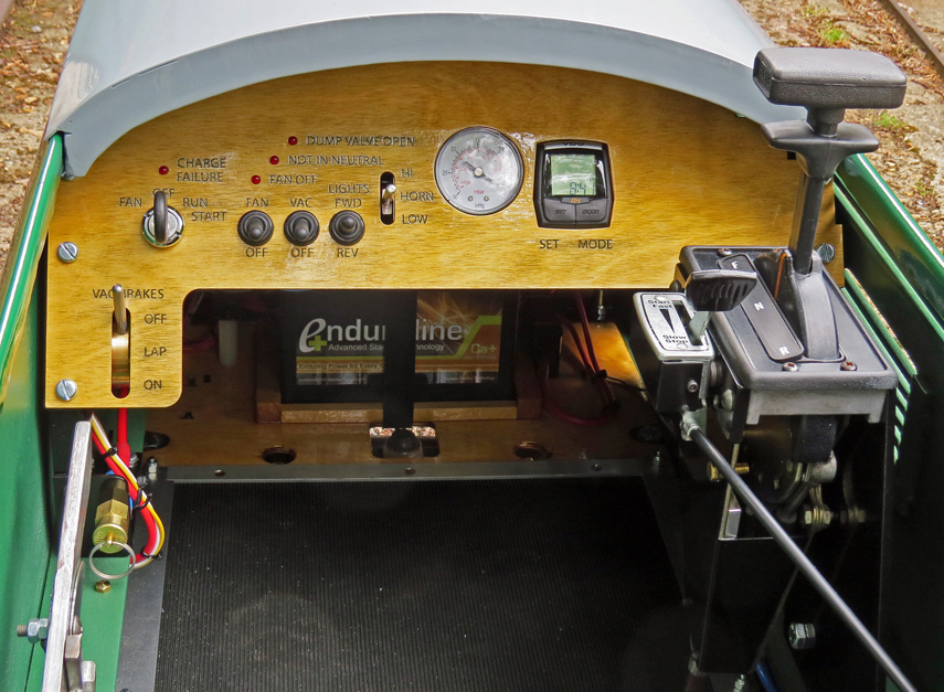
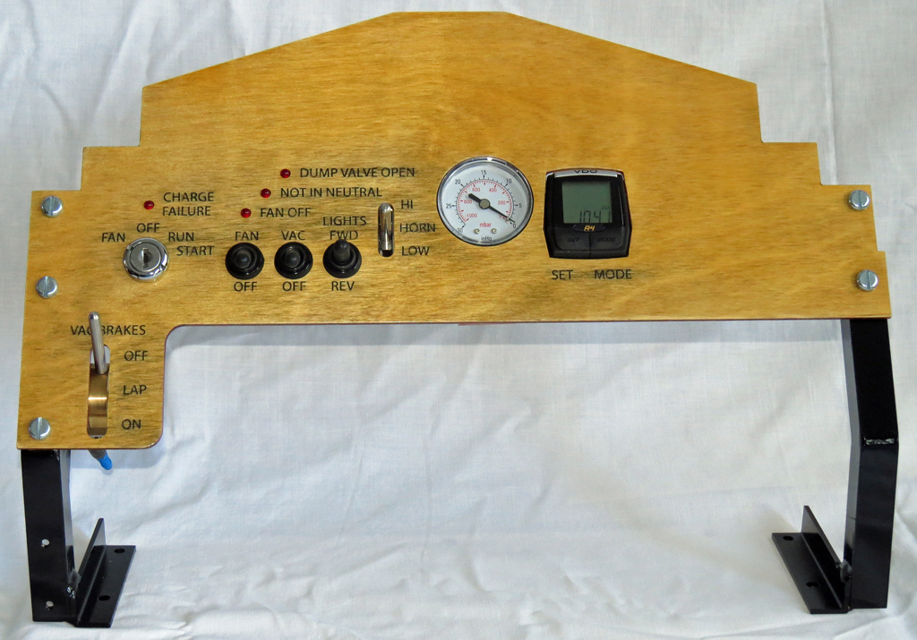 Here's
the new control panel ready for fitting to the loco.
Everything
is now fitted towards the left of the panel so that nothing is hidden
from the driver. The braking system has been swapped to
vacuum so
that it is compatible with the Pinewood Miniature Railway carriage
stock and the brakes are controlled by a brake valve supplied by
Station Road Steam fitted at the bottom left of the panel.
The
ignition switch and lamp are just above the brake valve with switches
to control the cooling fan, electric vacuum pump, and the running
lights centrally placed in the area visible to the driver.
The
vacuum brake gauge and a cycle "trip computer" to display speed and
mileage are to the right of the control panel. The diagonal
row
of three red LED's provides the driver with warning information.
Bottom left of the group is the LED to warn the driver that
he
has switched off the engine cooling fan. The middle LED of
the
three illuminates if the driver attempts to start the petrol engine
when the Hydrostatic Transmission control lever is not in the "neutral"
position, while the top right LED illuminates when the Hydrostatic
Transmission "dump valve" is open. These LED's and their
circuits
are features I have added to try and make the Hymek suitable for use by
the Pinewood Miniature Railway Society's junior members.
During
the rebuild I have incorporated interlocks to
stop the petrol engine or prevent it being started when unsafe
conditions exist, and these warning lights should alert unfamiliar
drivers to what they are doing wrong. The engine bay roof
which
carries the electric engine cooling fan has also now been fitted with
hinges (it used to lift off and potentially pull the wiring apart) and
an interlock switch on the hinge system switches off the electric fan
as soon as someone starts to open the lid. Hopefully that
will
prevent fingers getting cut by the blades of a running cooling fan. Here's
the new control panel ready for fitting to the loco.
Everything
is now fitted towards the left of the panel so that nothing is hidden
from the driver. The braking system has been swapped to
vacuum so
that it is compatible with the Pinewood Miniature Railway carriage
stock and the brakes are controlled by a brake valve supplied by
Station Road Steam fitted at the bottom left of the panel.
The
ignition switch and lamp are just above the brake valve with switches
to control the cooling fan, electric vacuum pump, and the running
lights centrally placed in the area visible to the driver.
The
vacuum brake gauge and a cycle "trip computer" to display speed and
mileage are to the right of the control panel. The diagonal
row
of three red LED's provides the driver with warning information.
Bottom left of the group is the LED to warn the driver that
he
has switched off the engine cooling fan. The middle LED of
the
three illuminates if the driver attempts to start the petrol engine
when the Hydrostatic Transmission control lever is not in the "neutral"
position, while the top right LED illuminates when the Hydrostatic
Transmission "dump valve" is open. These LED's and their
circuits
are features I have added to try and make the Hymek suitable for use by
the Pinewood Miniature Railway Society's junior members.
During
the rebuild I have incorporated interlocks to
stop the petrol engine or prevent it being started when unsafe
conditions exist, and these warning lights should alert unfamiliar
drivers to what they are doing wrong. The engine bay roof
which
carries the electric engine cooling fan has also now been fitted with
hinges (it used to lift off and potentially pull the wiring apart) and
an interlock switch on the hinge system switches off the electric fan
as soon as someone starts to open the lid. Hopefully that
will
prevent fingers getting cut by the blades of a running cooling fan.The control panel is constructed from Birch plywood, laser cut and laser engraved; the lettering being filled with black (using a 6B pencil) before the panel was varnished. It's the first time that I have tried this technique which, although much cheaper than having a metal panel cut and engraved, results in (at least to my eyes) an acceptable panel as opposed to a "perfect" panel. |
The Body |
| The
body was always going to be something that I had to subcontract for
grit blasting and paint spraying as it was simply too large (at over 8
feet or 2.4 meters long) for me to spray with aerosol paints in my back
garden. Naively I had imagined that blasting and painting
would
be the only work required, but I had missed the fact that the loco must
have been involved in an accident sometime in its past which had
resulted in a pronounced bend in the body panels on the left-hand side.
Sorting that out gave me the chance to practice panel
beating,
but I didn't expect to have to use a 4lb club hammer ! The
Mardyke body was certainly very rigid, which meant that the accident
must have involved some major collision or even a roll over.
Eventually I got the body straight and various loose parts
and
unwanted holes welded, with sanding discs on my angle grinder
creating nice smooth body contours. It was all
rather
reminiscent of those days I spent in the 80s building and maintaining
my Land Rovers. Many months later than expected I sent the
body
to my local "finishers" for grit blasting and painting. I can
really recommend Goldburn Finishers in Bordon, Hampshire, as they did a
superb job of spraying the various colours needed to create the classic
Hymek two tone green colour scheme. I think it turned into a
"labour of love" for them, and I know that they did their own research
into the full size Hymeks as well as following my detailed painting
instructions. Apparently having such a large loco on display
in
their workshop while they worked on it provided a great deal of
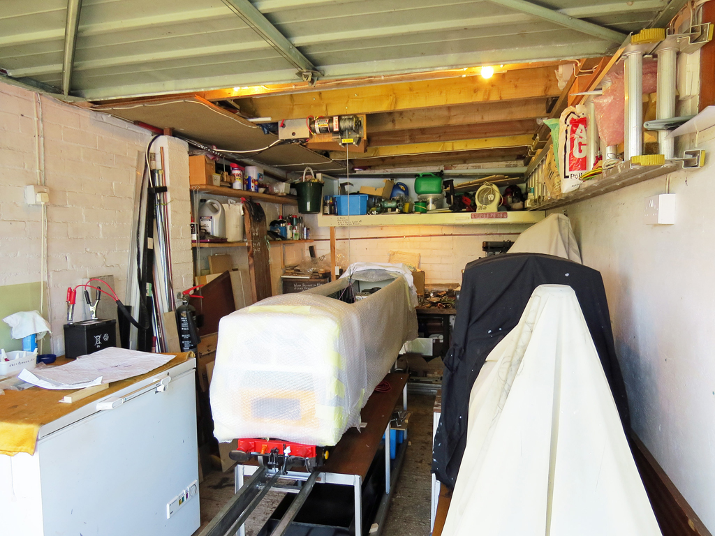
interest for their customers. When we dismantled the Hymek at Pinewood it took six of us to lift the body off of the bogies. When it came to reassembly I had to work out how to fit the body over the assembled power bogie by myself. Thankfully I still had the electric winch that had previously been fitted to my van to pull the 4" scale Tasker Traction onboard, and with a 2000lb pull rating it obviously would be able to lift the Hymek body. The photos below show the body being refitted, and literally the project was hanging by a thread during the process ! 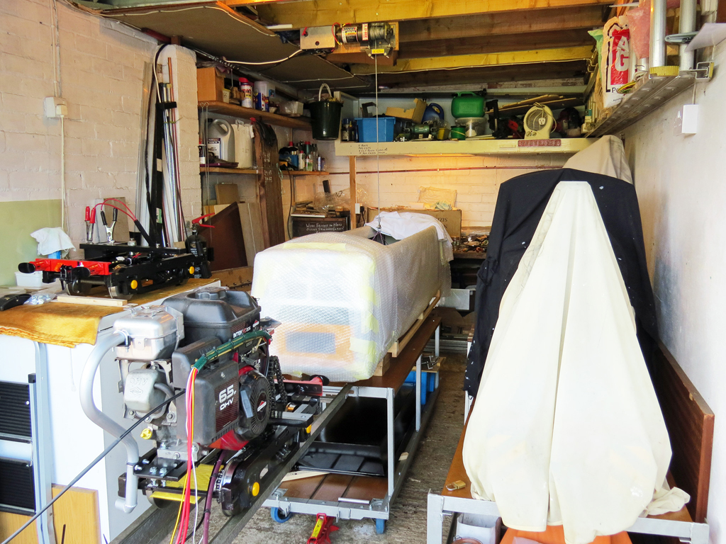 Here
the Hymek body is under the winch with the power bogie on my loading
bridge ready to roll under the body once it has been raised.
My
Stafford 'Gentoo' is under the covers at the right of the
photo
and you can see how little space was left to work around the two locos. Here
the Hymek body is under the winch with the power bogie on my loading
bridge ready to roll under the body once it has been raised.
My
Stafford 'Gentoo' is under the covers at the right of the
photo
and you can see how little space was left to work around the two locos. |
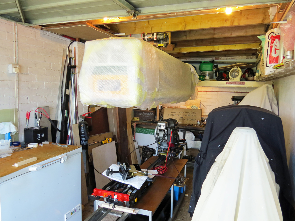 With
the body raised the two bogies have been rolled into place.
The
Hydrostatic Drive control which is permanently attached to the drive
bogie is resting on the unpowered front bogie. While I knew
that
the winch, its cable, and the Dyneema rigging I had used to
attach
the body to the winch cable were all adequately rated it was still a
nervous time. Having the painted body hanging like this just
doesn't feel right. With
the body raised the two bogies have been rolled into place.
The
Hydrostatic Drive control which is permanently attached to the drive
bogie is resting on the unpowered front bogie. While I knew
that
the winch, its cable, and the Dyneema rigging I had used to
attach
the body to the winch cable were all adequately rated it was still a
nervous time. Having the painted body hanging like this just
doesn't feel right.Perched on the freezer (which serves as one of my work benches) you can see the Hymeks new 12v battery being used to operate the electric winch which has been bolted to one of the garage roof beams. |
 After
five rather nervous minutes the body was safely attached to the bogie
bolsters for the first time in almost twelve months. All I
had
left to do was to cut the bulkhead I had made to fit between the engine
bay and the drivers "cab" to fit around the control cables.
It appears that when Mardyke built the loco they did not fit
a
bulkhead but I was doing so to try and aid noise suppression and also
to separate the driver from the engine. Priming and painting
the
bulkhead took over a week, and I couldn't progress the Hymek's rebuild
without it. With the project so close to completion that
seemed
like a very long week. After
five rather nervous minutes the body was safely attached to the bogie
bolsters for the first time in almost twelve months. All I
had
left to do was to cut the bulkhead I had made to fit between the engine
bay and the drivers "cab" to fit around the control cables.
It appears that when Mardyke built the loco they did not fit
a
bulkhead but I was doing so to try and aid noise suppression and also
to separate the driver from the engine. Priming and painting
the
bulkhead took over a week, and I couldn't progress the Hymek's rebuild
without it. With the project so close to completion that
seemed
like a very long week. |
Horns & Vacuum Brake System |
 In
the photo on the right you can see a black framework on which many
parts are mounted. All the parts had been fitted for a trial
assembly before things were painted, but assembling it and then
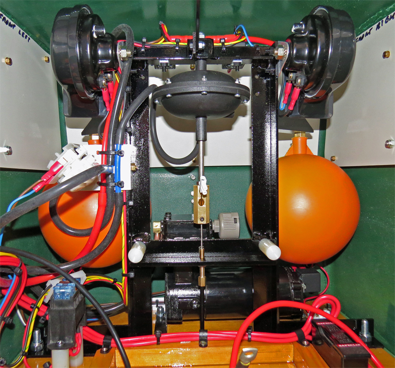
managing to fit the wiring and plumbing turned out to be a lot harder. In
the photo on the right you can see a black framework on which many
parts are mounted. All the parts had been fitted for a trial
assembly before things were painted, but assembling it and then
managing to fit the wiring and plumbing turned out to be a lot harder.On either side at the top are the High and Low tone horns with their respective power relays, and hanging dead centre is the PNP vacuum brake servo which operates the brakes on the front bogie (the rear bogie brakes have their own handbrake in the drivers compartment). The two orange spheres are reservoirs for the vacuum braking system; the one on the right serving the vacuum brake servo and the one on the left being connected directly to the electric vacuum pump. Having a reservoir connected directly to the pump gives the pump a significant volume to evacuate which stops the vacuum limit switch chattering (a problem I have seen on many electric vacuum pump systems). The two reservoirs are actually 6" diameter ballcock floats fitted with homemade pipe connectors, and you can buy both and still have money left over compared to the cost of the traditional commercially available vacuum reservoir. The rather over exposed (shiny) thing halfway up the left hand support is the vacuum limit switch that controls the electric vacuum pump which can be seen behind the support frame. The 12 Volt battery will eventually be fitted in the framed area in the foreground, and the main and individual circuit fuses are fitted respectively to the right and left of the battery tray. Totally hidden by all of this are the LED locomotive running lights and their junction boxes. Wiring and plumbing this assembly took over 11 hours mainly because of the space limitations and the need to ensure that the assembly had suitable wiring and plumbing connectors to permit it's removal if / when service is required. Fitting the entire plumbing and wiring system for the Hymek has taken almost a week which seems like a long time, but in reality there is more to fit and wire than on some of the Land Rovers I used to build and race in the 1980's and they had considerably more space to fit everything in to. |
Finished (at last !) |
 This
photo shows a drivers eye view of the controls of the completed Hymek
and if you compare it with the photo earlier on the page you can easily
see the differences. The throttle and hydraulic drive
controls
on the right are still in the same position, but have both been
enclosed with aluminium covers to stop things digging into the driver's
knee. The silver coloured bar on the bottom left is the
handbrake
lever, and the brass object with the ring on it beside the handbrake is
the vacuum reservoir release valve. The dashboard has already
been described above, and it always amazes me just how many wires (and
vacuum pipes) converge there. The dashboard was also the very
last item to be wired up, so it was rather annoying to discover that I
was one wire short ! Having to install the missing horn wire
into
the already "loomed" wiring was a somewhat awkward task especially as
the wire should have originated at a connector behind the Horn
&
Vacuum Brake assembly described above. This
photo shows a drivers eye view of the controls of the completed Hymek
and if you compare it with the photo earlier on the page you can easily
see the differences. The throttle and hydraulic drive
controls
on the right are still in the same position, but have both been
enclosed with aluminium covers to stop things digging into the driver's
knee. The silver coloured bar on the bottom left is the
handbrake
lever, and the brass object with the ring on it beside the handbrake is
the vacuum reservoir release valve. The dashboard has already
been described above, and it always amazes me just how many wires (and
vacuum pipes) converge there. The dashboard was also the very
last item to be wired up, so it was rather annoying to discover that I
was one wire short ! Having to install the missing horn wire
into
the already "loomed" wiring was a somewhat awkward task especially as
the wire should have originated at a connector behind the Horn
&
Vacuum Brake assembly described above.Thankfully once the wiring was completed every feature worked when tested. All that remained was to fit the loco numbers and nameplates. Finally on the 367th day after I had started work the Hymek was completed and three days later, having managed to squeeze it into my VW Caddy MPV, the Hymek was tested at Pinewood. The loco worked perfectly pulling empty coaches around the track, but subsequently proved to suffer from a lack of tractive effort when it started to hail passenger trains. Initially it wasn't clear if the problem was caused by the EATON hydraulic unit or by some other factor, but testing soon showed that it was simply a case of the drive wheels slipping on the track. Despite its size and weight the Hymek is rather a poor performer when it comes to hauling passengers around Pinewood as even on dry track it is quite difficult to find enough traction to drag two loaded coaches out of the station despite having 6.5 horse power available from the engine. As designed by Mardyke the four driven wheels on the power bogie have no suspension to keep them all in contact with the rails, and even with the best laid track I would guess that only one wheel on each axle is really carrying the weight of the engine. The end result is effectively a two wheel drive locomotive and that is never going to be a load puller. |
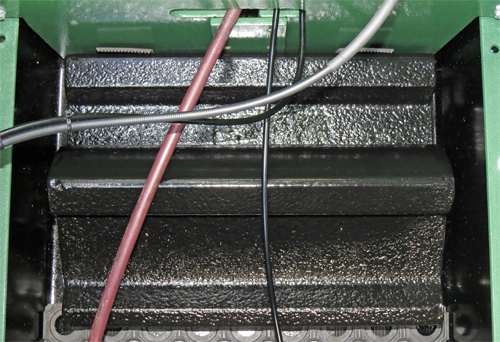 Postscript. After locating
an Internet forum devoted to Mardyke locomotives I learnt that this
type of Mardyke locomotive is well known for its lack of adhesion, but
I also learnt that when sold they are fitted with about 37 kilos of
ballast in the rear of the footwell to improve traction. My
Hymek had
obviously lost that ballast before I purchased it, but thankfully I'm a
volunteer on the Mid Hants steam railway permanent way gang so I was
able to source some lengths of old rail to create new ballast.
The photo shows two of the lengths of rail fitted into the
footwell, and more have been fitted on the other side of the bulkhead
just
in front of the rear bogie. With a total of 68 Kilos of steel
ballast onboard the adhesion has been greatly improved and the loco can
now pull a loaded train quite smartly out of the station. Postscript. After locating
an Internet forum devoted to Mardyke locomotives I learnt that this
type of Mardyke locomotive is well known for its lack of adhesion, but
I also learnt that when sold they are fitted with about 37 kilos of
ballast in the rear of the footwell to improve traction. My
Hymek had
obviously lost that ballast before I purchased it, but thankfully I'm a
volunteer on the Mid Hants steam railway permanent way gang so I was
able to source some lengths of old rail to create new ballast.
The photo shows two of the lengths of rail fitted into the
footwell, and more have been fitted on the other side of the bulkhead
just
in front of the rear bogie. With a total of 68 Kilos of steel
ballast onboard the adhesion has been greatly improved and the loco can
now pull a loaded train quite smartly out of the station.Sadly after operating passenger services at Pinewood on just three occasions I left the society, and due to the lack of use and difficulty of transporting such a large locomotive I decided to sell it. As is so often the case the Hymek sold for much less than it cost me to buy and restore it, but I know that its new owners will be making good use of it. If you want to follow the Hymek's progress then take a look at the Fancott railways website at www.fancottrailway.co.uk or their Facebook page at www.facebook.com/FancottMiniatureRailway |
Photo Gallery |
The
photos below were all taken by Pinewood member Paul Konig during the
Hymek's trial run at Pinewood on July 6th 2014. To watch a short video of the Hymek running at Pinewood click here.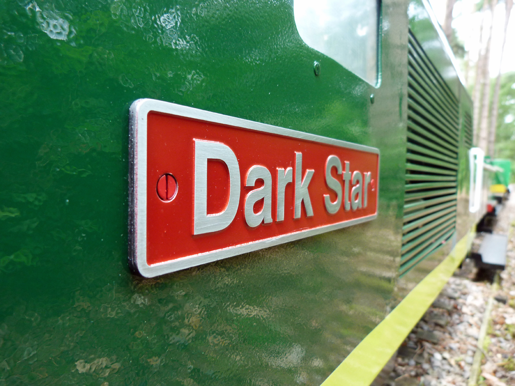 |
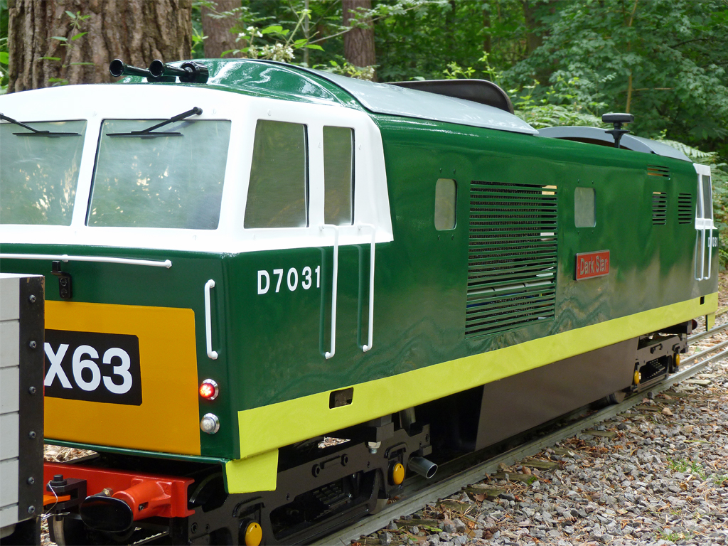
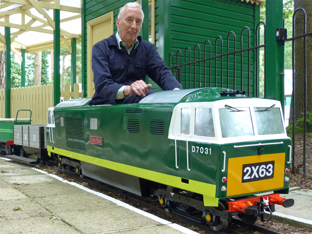 'Dark Star' ready to depart from Pinewood Central station. The wagon directly behind the engine is there to stop young passengers from trying to remove the rear windscreen wipers. |
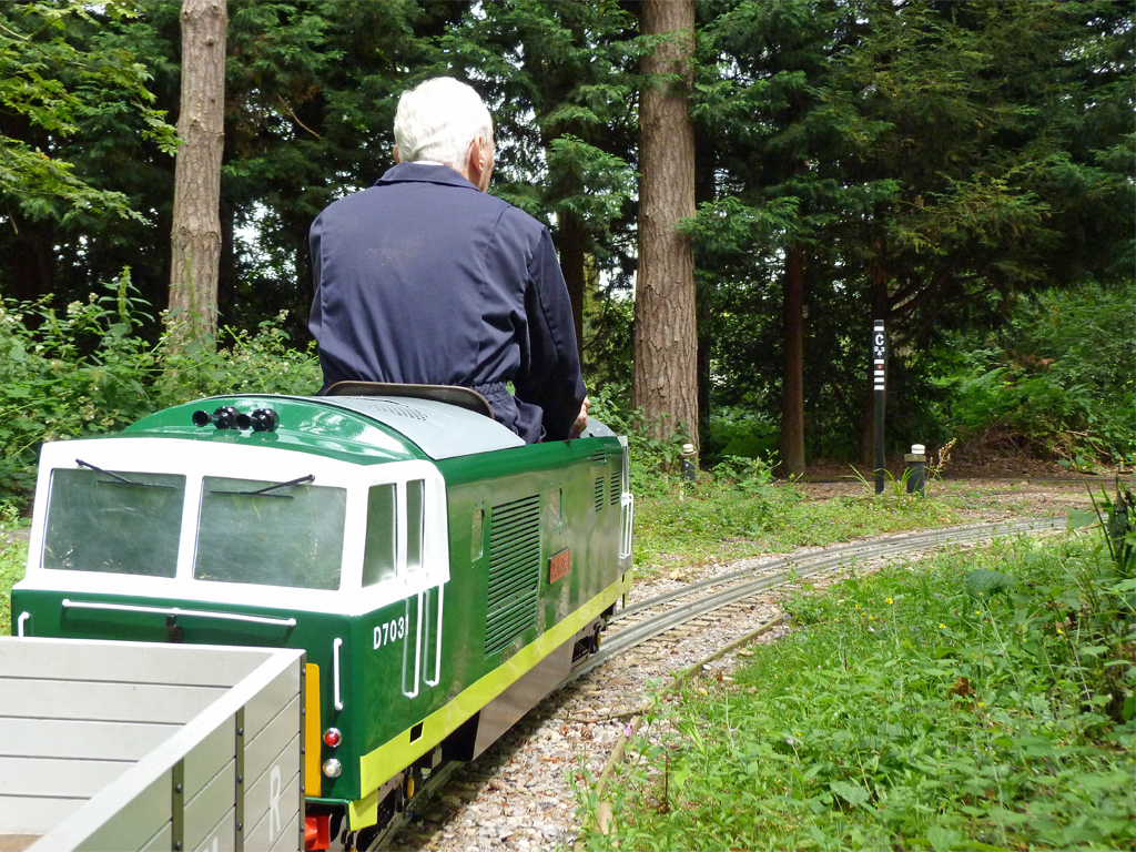 In this photo you can see how the Mardyke design has tilted the loco body (the wagon is riding "flat" on the track) into the turn to aid stability. |
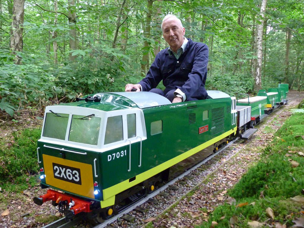 The lighting on 'Dark Star' is now all done using LEDs. |
 In this photo you can see that the windows give a nice reflection without letting you see through (or looking like mirrors). The windows have been made from mirror finish polycarbonate with the surface lightly rubbed with fine wire wool. |
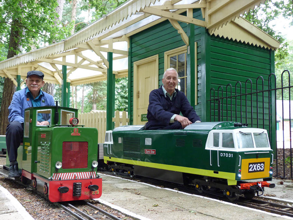 Pinewood's two passenger hauling petrol / hydraulic locos together in the station. |